VW Beetle Conversion

SHIFT EV is converting this 1970 VW beetle to electric power for a customer from Washington state. VW Bugs have been a popular platform for conversion to electric for decades. What sets this apart is its range. This article was created to allow the customer to follow the high-level build activity. It is not a comprehensive step-by-step procedure, but we have included many details that future builders will find useful.
Design goals: (customer-driven goals)
- Range: 150-200+ miles
- Acceleration: Better than stock
- Instrumentation: speedometer is stock, the fuel gauge will display correct State Of Charge (SOC). The stock red "Oil light" becomes a system "Fault light". The stock yellow "Generator Light" becomes a system "Power Limit" warning light".
- Charging: SAEJ1772 Level 1&2 (110VAC and 220VAC)
- Heat: PTC (electric) heater, Operated by stock heater controls
When evaluating battery type and size we consider the energy consumption rate of the vehicle for typical driving. Many VW Bugs have been converted in the past with efficiency claims between 200 and 300 Watt-hour per mile (Wh/mi). Many variables contribute to this efficiency such as weight, tires, motor efficiency, speed, etc. To determine battery capacity we use the upper and lower ends of our range goal and multiply them by the estimated 250Wh/mile.
(250Wh/mi) x (150 miles) = capacity of 37,500Wh, or 37.5kWh
(250Wh/mi) x (200 miles) = capacity of 50,000Wh, or 50kWh
With target battery capacity understood, we evaluate weight total and distribution, location, crush zone safety, etc. If that is feasible, we review available motor and controller/inverter solutions that can provide the efficiency and power within budget for this application.
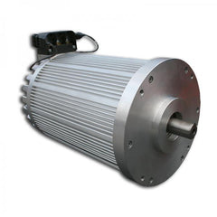
In this case, we narrowed it down to one of the smaller HPEVS brushless AC motors or one of the NetGain brushless SRPM AC HyPer9 motors. We settled on the Hyper9 X1 system. That locks us into a maximum and minimum voltage range that our battery pack and other high voltage components must provide.

After reviewing a few types of batteries in different scenarios, the Tesla battery modules used in the Tesla Model S and X are a good option for this build in several ways.
- Commonluy used Tesla S and X battery modules are about 5.2kWh (depending on some model variants sucy as the 4.5kWh, 5.3kWh, 5.6kWh, and 6.2kWh.
- For this exercise we'll use a conservative 5.2kWh capacity value x 10 modules = 52kWh of capacity. That's 2kWh more than we'll need.
- They have a high energy density, meaning they're more compact relative to many other batteries.
- They're capable of more than enough power that our system will draw 750A.
- As long as healthy modules are purchased, they're a good value at around $230/kWh on today's market.
- We can accomplish our drive systems maximum and minimum voltage range
- With 5 modules wired in series, the full and empty voltages fall within the operating range of our motor controller. To use all 10, we'll run two strings of 5 modules this way, in parallel. During discharge, one string will its + and (-) outputs in parallel with the other string. To avoid hazards is critical to have a BMS that properly monitors and manages the two strings and decides whether each string is allowed to connect the DC output bus that is used by the motor controller or any other loads. For more on this surprisingly complex topic, see the Difficulties with parallel strings section of this document by Orion BMS.
With the high-level system decisions finished, we move into how we're going to properly and elegantly fit and wire these parts in the space available. Beginning with the battery pack(s).

Above is a mockup of the outer-most dimensions of our proposed battery box shape. This is a cost-effective way to verify fit. Movement of the side panels on the all-thread rods allows room for adjustments.


Five-Module battery box for the rear.

Five module battery box resting in place. It will move rearward a bit more on the final assembly.


Modules exposed.

Extracted modules are stacked on a pallet behind the empty battery tray.

Some other useful parts are recovered from the Tesla pack, but most of it (metals) go to our local recycler.

10 Tesla S modules will go into the beetle (16 modules are pictured).


Other things worked on:
- Updates to wiring diagram to reflect this build.
- Located all nonlabeled wires (16) and isolated them with tape for a 12v power-up test. They'll need to be traced and decide what to do with them later.
- Powered up 12v systems & verified what works:
- horn
- brake lights
- turn signals
- headlights
- headlight dimmer switch
- speedometer light
- windshield wipers
- What didn't work:
- dome light (switch)
- glove box light not working
- didn't check courtesy light switches (door switches), hood light, trunk light, or license plate light.


Since the last post, the high voltage cables have been pulled from the front to the rear.


The images above show the rear battery box coming together. The top-left and the two bottom-right images show the box sitting upright. The rest show the box tipped on its back while revising. The base bolt holes (originally slots) were where we planned to bolt the box to the floor. The revision is the addition of the rivet-nuts being fitted and fastened to the base. This will ease assembly, reduce parts and be a bit more strong.


Much of last week was spent researching the best PTC components to assemble at least a 1.5kW heater system that will fit in the available spaces without crowding the passenger compartment. Most heater system parts have been ordered. The under-the-hood ductwork will be ordered when we see what parts and shapes are needed to mate with the dash kit ducts.


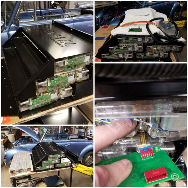
This image shows the black 3D printed board using scavenged connectors from a TESLA slave board. The green board is a TESLA slave board (which we don't need) where we are testing the idea of using its connectors, without removing them. We're looking for the most stable way to make our connections considering serviceability, visual inspectability that connections are seated completely, and a few other things.


As discussed before, the new tires are slightly wider than stock. Because of that, we discovered that the spare tire doesn't quite fit into the stock VW space. So we'll be exchanging the spare for a slightly narrower tire.
The dash parts arrived, except they forgot to ship the main large part. I reached out to the vendor and they've responded positively. It should arrive early next week. We haven't received the stereo parts yet.
This was a busy but unproductive week at the shop. One day was spent preparing for the film crew for the pilot called "EV Rides" and the following two days were spent with them at the shop and out getting moving shots with past customer projects. Without air conditioning, it was above 90 degrees in the shop so not much happened there this week. The film crew was interested in this car and recorded some video, but the story they had in mind seemed to focus on finished cars, so I don't know if they'll feature shots of this car or not. They said it would be a couple of weeks before they publish. If scenes are using this car, I'll post links to the video here when it releases.

The big box of goodies from the Stereo order turned out to be missing the radio unit. I spoke with the vendor and they knew it and said it's on backorder and should ship in 1 to two weeks. I'm a little bummed because we wanted to get that dash in before the front battery box is complete.
The P100D battery modules are missing some plumbing fittings and some of the plastic clamshells that protect them. The seller didn't specify that they "were" included. It is just standard protocol and I made an assumption. I'm working to source those parts. We have enough to assemble the rear battery enclosure and that is now wired and the other end (plumbing) will begin Monday. I expect to have that battery pack in the car early next week.
The heater has been challenging. I've purchased several different types of heater units that I thought might be slick for the limited space. I'm not satisfied with any of them being under the hood requiring big vents or tubes through the wall above the knees.


 This image shows the high current cables (orange) and cell tap/thermister harness installed. The cell tap wires (small red, yellow, orange) will be secured more. The bottom right cable coiled up is the Negative end of the pack. The positive high current cable (not shown) will connect at the upper right, then the side cover goes on! The plumbing on the other end will go much more quickly.
The final cable is on the rear battery pack, the BMS and temperature sensor wiring are all secured. Wiring is pulled through the firewall tube of the box end cover. That side is assembled and bolted into place. On the other side, we are plumbing the modules from a 100kWh pack (6.3kWh each). They have twice the connections and odd-sized fittings as compared to the more common Tesla S modules. We have all the hose, connectors and manifold plumbing sizes figured out. But when we wired and plumbed it yesterday and connected a pump to check for leaks. We found no leaks but discovered this pump won't work with these modules. A second pump (different type) wasn't good enough either. Both of these pumps have garden-hose-like flow, but we need higher pressure. When the flow is restricted too much on these pumps the pressure drops. That's why we test before we button up.

These images show how we are attaching the high voltage junction/fuser/contactor box (and all other parts mounted to the rear firewall of the Beetle. All fasteners are threaded rivet-nuts. We drill a hole and rivet the nut into position. This way, the fasteners can be removed from this side without having to remove the battery pack on the other side of this wall.
On the right, the two 6-fuse low voltage (12V) fuse blocks and 3 diode-equipped cube relays for the rear of the car are mounted on the door of the high voltage box. Inside the box, an aluminum plate is cut and drilled to accept two contactors, a high-voltage fuse for the rear pack, a high-voltage relay at the top, and our positive high-current battery input cables (not routed here yet). This had to be mounted to cut and crimp their ends to the exact length needed. The gland nuts for the cables to pass through are also installed. When the plumbing is finalized, the rear pack will go into the car.
More high current cables were routed, crimped, and installed by Chris. We've had concerns with the pressure required for the P100D Tesla modules not being good enough with typical pumps. We are experimenting with a higher pressure pump. We've tried other pups, some in series, etc, trying to get the coolant flow up to par. We must find the solution that we'll install so we can check for leaks in the rear module (and front) before they go in. We can't put them into the car until this is confirmed. The delays to research and test options are sometimes disappointing but must be done.
The throttle linkage and location were determined, a few parts were fabricated and polished (since it shows). It's about an hour from being installed and done, but it took much of a day to get the linkage and cable extension that would work. It all is looking super neat and tidy. The radiator, throttle, and possibly a pump or two have been included in the custom CAD design for the engine compartment floor plates. Those plates will be ordered on Monday.

Unlike other beetle conversions, this will have 63kWh on board. That battery pack consumes a lot of space where other conversions have had room for luxuries like a heater. During this project, we have explored many ways to get good heat in the remaining space. That includes custom enclosures, multiple heater units, a center console to hide stuff and add fan controls, which the original car never had. After sitting in the driver and passenger seats imagining a center console, one begins to realize the small car would feel very cramped for average-sized or bigger people. The center console remains a valid option to put around what we've done if it remains appealing. We went with a 3kW off-the-shelf heater/fan unit neatly tucked under the firewall in the center. Having open space below it feels roomy. Having the heater in the cabin (vs. under the hood) will allow it to recirculate the cabin air, heating more effectively. The left and right side duct tubes will get replaced with directional and closable vents. Hot air will also be ported to the windshield defrost ports. Closing the lower vents will send all the hot air to the windshield.
There are no big roadblocks anticipated regarding parts. But as we build, a few things are requiring a bit more attention or follow-up than expected. This is routine and is getting worked out. While they're not big nor long delays, today's updates are dedicated to a few of those things, listed below.
- The heater assembly that was recently been decided on has been back-ordered due to an unavailable 12V blower fan. I'm told it's coming, but In the meantime, we've been using one that we had on the shelf with the same outer dimensions, but a wrong pack voltage element.
- Most coolant connectors for the Tesla P100D battery modules were included in the shipment. There are 4 needed per module. With typical Tesla Model S battery modules, these connectors are not needed nor included. But the P100D connectors are different and have no good alternative. I have been calling battery suppliers and posted on social media yesterday that we need 17 of these, plus 3 clamshell tops. I'm also reaching out to a local traveling Tesla tech to check new part availability. I've created a page to clarify the difference for this topic and to give early warning to builders considering these modules. As of today, I found new connectors for €9,50 each, but am continuing to check around.
- Heat and windshield defrost ducts for Classic VW type 1 are well known for having issues. A lot of time went into exploring how to add a simple and reliable electric heat source while also being able to plumb the air to the existing vents. This week we began executing the plumbing strategy. We'll pop a hole in the top surface of the heat box (pictured a few paragraphs above). Another hole will go through the upper firewall panel above it. The 3D printed manifold pictured below will port air directly from the cabs heater box to feed 4 ports with short tubes to the windshield defroster vents. Sourcing duct hoses of the proper size and adapting at couplers where needed was the challenge. We modified the 3D print port sizes to make use of stock VW hose sizes and repositioned the ports to clear the battery box and other obstacles. Thankfully one tube was supplied with the car that we could use to verify dimensions. More hose was ordered and the latest 3D airport is being printed (lower left) as I write this update.

-
Engine bay floor pattern (CAD) was sent at a local laser cut shop to get us a thin pattern to verify the latest CAD geometry we have will fit, and receive the part planned to mount to it properly. This shop is usually a next-day lead time. Unfortunately, the CNC programmer had an emergency come up and has been out for two days. I spoke with him today and we should have parts Monday.
- Correct coolant pressure and flow rate through the Tesla modules is an important part of the conversion. We've been doing some testing on the plumbed rear box of 5 modules and have learned that an upgraded pump will likely be needed. To verify the minimum requirements, we're going to fill and test the modules within the front and rear battery boxes on the bench (as a whole system) before installing them.
This week's emphasis for Chris and I was on getting the new foam dash and related parts cleaned up, and installed. As previously discussed, the front battery box will block much of the access to dashboard switches, wiring, and fasteners. This makes restoring it a priority.
While the car has new paint, there were unpainted areas under the windshield that would be exposed with the replacement dash. We masked and painted that flat black. Other detailed work included cleaning all knobs with a toothbrush to get 50 years of grime out of every crack.
The metal grill's beside the speedometer and the glove box were sandblasted, but rust pitting still showed on the bare steel. After more sanding, they're painted and installed. Through the slots of the metal grilles, a new coarse stainless cross-link mesh shows a nice contrast. The glove box and other fasteners were replaced with new stainless steel.
The original heater knobs did nothing when we got it. They were crudely held in place with bolts jammed into them from behind. Originally they each opened and closed air valves. The cable control mechanism that they once connected to was missing from behind the dash, but we don't need it. We 3D printed an adapter to mate the original left knob to the half-moon shaft of a new rotary switch. The switch will enable a PTC electric heater element by powering a contactor, and the fan speeds.
The side vents of the new heater box pictured previously in this article may be opened or closed to change the proportion of hot air between the defrost and footwell spaces. The right knob is mounted firmly to fill the hole in the dash. Turning it won't cause it to loosen nor be harmed.


We now have enough P100D top clamshells to assemble the front pack and will begin that next week. We can't button it up until the P100D coolant connectors arrive and are verified for proper fit and pressure testing completed. I've updated the P100D module coolant connector page with further details discovered this week. I've ordered what I believe to be the correct connectors, and have received a shipping confirmation.
Routing of all the low-voltage power, signal, and data wires needed from front to rear went quickly.

The image above shows a draft part representing the drivers' side engine compartment floor panel resting in place. It was produced from thin aluminum to verify edge geometry and other features such as radiator mounting, etc. From this, the CAD models were updated as shown in the bottom image, and the final stainless steel parts are being laser-cut as I write this update.

Until this week, we were using a heater box that we had in stock to mock up the system. Its PTC element was the wrong voltage, but everything else was identical. The proper heater box arrived, and of course, it's not black (a must). It was scribed for the defrost porthole and cut (upper left), painted black, and bench tested with the 3D printed ductwork to confirm higher temp plastic isn't required (upper right). The 12V heater fan wiring harness was completed, secured, and tested by operating the 3-speed switch on the dash. The airflow to all six ports is excellent. The defrost air flow at the windscreen is impressive.
Some Tesla Model S and X battery modules have wires from each of the 6 bricks inside to the connectors at the green slave boards. In a Tesla, these boards monitor and balance the module as coordinated by the main Tesla BMS. Some versions have a more fragile flex circuit (Kapton and traces) like the modules pictured that we are building with. When we began to route our Orion BMS cell tap wires, we discovered one module had a torn-off flex circuit (bottom right). Disappointing, but a part of the journey. The box needs to be disassembled to get a better look and decide the best way to make a new reliable BMS cell tap connection to the bricks in this module.
Once the wiring of the front box is complete, we begin connecting the coolant lines for both front and rear battery boxes to run the whole coolant system on the bench. Yesterday I received tracking confirmation that the coolant connectors and hose arrived in the US and hope to see them arrive next week.

The stainless steel panels arrived with a dull eggshell finish and minor scratches. Directional grain texture was added and was just aggressive enough to work through the scratches. The two large flat panels got three folds each and were ready for test fitting. Minor trimming was needed, but the parts fit into place well. A final assembly of parts in the motor compartment is underway.

The new connectors for the special P100D Tesla modules arrived, and I have test-fit one on a P100D module.

The press-fit of the nylon hose onto the connectors requires a special tool with a 3 week lead time, and a pretty penny. It takes a lot of force and without the tool, it is a lot like pushing a rope. Rather than wait for a tool, I looked up some clever ways people have accomplished similar press-fits like this. A homemade fuel-line tool on this z28 thread gave me an idea. A couple of hours later I was printing the orange parts in the image that are nested into a standard caulk gun. Solutions like this are often a gamble, but it worked great. Thirty minutes later all 10 lines for the front box were pressed onto the Tesla P100D modules.
Click here to view more details about the P100D 6.3kWh coolant connectors in a separate blog post.
To check clearances for the custom heater ducting and behind-the-dash access we put the front battery box into place one last time (as empty). The spare tire wouldn't fit. It's not the box in the way. It's the new wider tire on the new wider rim. The new rim will fit, but we need a narrower tire on it. I dropped it off at the tire store to return the tire and have it replaced.

A few paragraphs above I mentioned a broken cell-tap flex-circuit on one of the battery modules. These are critical for the BMS to monitor and balance the pack and a reliable fix is important. Since replacement parts are not available, some careful scraping exposed the flex circuits gold surface under the transparent Kapton coating. Then a fast touch with a fine tip solder iron is all it took to wick a nice solder bridge across each tear. Another spot nearby was beginning to tear also, so it received the same treatment. The affected area was cleaned with isopropyl and sealed with Conformal Coat. Before connecting it to the slave BMS PCB this and all other cell tap connectors were inspected and probed to be sure no other tears were present. The lower right image shows it repaired and plugged into the slave BMS PCB on the module. It is very stabilized once in place, and it is not relying on the solder bridges for mechanical strength.
The assembly of the front box remains the priority. Here's a status update:
Mechanical fit: It was assembled mechanically with modules, but without plumbing and wiring. That went together as planned.
Damage was discovered and fixed. While Chris was installing the cell tap wiring of the assembled front box, he discovered the torn cell tap circuit. The box had to be disassembled to repair it (as described above).
Slave BMS PCB modifications & cell tap harness wiring. Since the flex circuit repair, all of the slave BMS PCBs have been modified (traces cut). This way, we can solder our cell tap wiring harness to the exposed side of the mounted BMS slave PCBs in place on the modules, without extra handling of the board, connectors, and flex circuits. The PCBs are all mounted and ready for harness wiring.
P100D Coolant connections and routing to manifolds. Before cutting and assembling the coolant line to the new connectors, the minimum lengths from each module to its coolant manifold must be understood. This length changed because the plumbing side of the front box was designed, fabricated and powder coated before we switched from standard Tesla modules to the P100D modules. The box side-cover has slots intended for plumbing to exit, but those slots don't line up well with the P100D fitting locations. There must have been over 20 pages of sketches exploring possible routing to avoid the delay and cost of a new box side panel. The space in the box is very constrained, making hose overlaps a pinch risk. The nylon coolant line is not very flexible. With t the tightest allowable radius at about 5" or 6" they need to exit near the connections on each module. All this to say it was more difficult to accommodate the P100D coolant line routes than expected. We now have a routing plan and are proceeding to assemble!
The front battery is nearly assembled. The cooling lines are in and had to be heated and hand-formed to route them inside the box before exiting the side. This side lid was made for the standard Tesla modules that we expected to use at the beginning of this project. The slots don't line up quite right for the coolant connections found on these P100D modules. The series connection cables are all installed. The fasteners are mostly in place. Of course, a few odd sizes are needed in some places, so those will get picked up and installed next. Otherwise, what's left is to make and install the cell tap wiring harness and the thermistor (temperature sensors) harness.

Two 1" holes have been drilled into the floor pan tube under the battery in front, and two more in the back of the tube to bring the lines out of the floor pan tube. Next, we'll be pulling and connecting these two main coolant lines, connecting the pumps, and radiators.


With the mystery wiring and accomplished much of the low voltage (12V) wiring in front is complete. We installed an easily accessible, and isolated 12V+ post under the hood, and a common battery (-) post to the chassis. These points will power our new unswitched loads in the front. Only one low current 12V+ tap was necessary to add to the switched pin on the stock fuse block.
The inertia switch, a relay, and several in-line fuses were installed. The multi-pin connections and wiring from the charger, DC to DC, contactors, and battery management system (BMS) in front are mostly wired. There's another day or so of wiring upfront before the front battery can go in, then the last few wires can be cut to length and connected. It's a nice milestone to have all the stock 12V systems and a few of the new systems working.
The cabin is completely wired except for two dash-light connections from the rear BMS unit to two stock instrumentation harness wires under the rear seat on the drivers' side. The old Generator light will now represent a Power Limiting signal from the BMS. The old Oil light will represent a BMS Fault. Under the rear passenger seat now sits a 30ah 12V AGM battery, fused and wired. This fuse serves the dual purposes of high current protection, and it's easy to isolate the 12V battery for long-term storage if desired.

Left two images: The triple high-voltage fuse holder was mounted to the front battery box. This is for DC bus voltage that goes to the DC-DC, HV Charger, and PTC Heater element. The front battery pack is completely wired and install-ready except for two wires that need to be cut to length after it's in position.
Middle Images: Under the hood, there was a bit of rust spot repair & paintwork which can't be easily accessed later. The example pictured is the brake reservoir tray that got a quick clean-up.

For the protection of the onboard EV electronics and wiring, the stereo amplifier was installed now. It required minor hole drilling and insertion of rivet-nuts for mounting the amplifier before the battery box goes in. This reduces the risk of an installer causing unintentional damage trying to mount and wire it. The stereo and amplifier are now wired, except for the amplifier's output speaker wires. This will be easily accessible for whoever finishes the car interior after the EV conversion work is complete.
The wiring under the hood is being neatened up a bit further, and all connections double checked. Then the front box goes in. The high-voltage wiring in the entire car is now done except for connecting to the front battery. While I've concentrated on the front, Chris has been wiring the BMS and traction Motor Controller/Inverter at the rear of the car.
The front box is in!
It went in exactly as expected, thanks to a great deal of preparation the past few weeks.
There are still a few electrical and plumbing connections to make before we can put the hood on and say the front is 100% complete. But it's close.
The car was rolled back and forth to be sure the suspension had settled. No ride-height adjustment was needed from the stock torsion bar position.

To protect the batteries, the BMS won't allow charging below 5C. Since the car is going to Washington, that could be a problem when plugged-in cold. We decided to add a water heater circuit to the system (under the motor bay). It will warm the battery pack while and/or driving if the battery falls below a pre-set temperature threshold. It won't run the radiator fans (4) if it is in battery-warming mode. And it won't add heat on a hot day. This is all simple analog and operates without the driver needing to do a thing.
Wiring in the rear of the car continues and it should be picture-worthy next week.

We tried to fit two different styles of Hall Effect pedal assemblies both in the footwell, as well as in the engine bay. Neither was a good match, and both took away from the classic look and feel, even trimmed. So we're sticking with the original plan and a stronger spring.
We hosted a local open house Wednesday night and the Beetle was very well received by the crowd. It makes people smile.
I've been out for a week, but the new return spring for the throttle arrived and was installed, and the throttle was reassembled. Chris completed the wiring from the throttle, its microswitch and the motor controller CAN wiring. Nothing very picture-worthy this week. Next week will be much more productive, and a more interesting update.

The former engine bay (lower left) shows a few harness wires exposed that we will use to adjust profiles and settings when drive testing begins. It also shows the completed throttle control and wiring, visible above the two left fans.
The CANOP isolator (upper right) is mounted and wired. It is on the CAN network between the BMS and the motor inverter/controller. The battery is wired also, but still waiting for its mount to be fabricated. All this wiring will be loomed after drive testing.
The bottom right image shows the wired and labeled 12V fuse blocks and 12V cube relays in the rear of the car. We use relays that have built-in diode suppression to prevent spikes from damaging sensitive devices on board.
The pump and fans need to be wired next. Then we power up the 12V systems and begin programming the BMS and motor controller. The pump and fan wiring are already routed to the bottom of the car, making it hard to go home without finishing that step tonight.
We began powering up the 12V system with sensitive or powerful equipment such as the motor controller, BMS units, and high voltage batteries intentionally disconnected. The "live" BMS cell tap harnesses have never been plugged in. The 12V battery was connected to test the full 12V harness for the first time, with a minimal in-line fuse to protect wiring and components if things weren't correct. The 12V system powered-up on a temporary 5Amp fuse. The whisper of the coolant pump could be heard humming. There's no coolant yet, so we pulled its fuse. One at a time, the LED running lights, heater fan, stereo head unit, windscreen wipers, etc, were tested. The headlights would have blown the 5A fuse and will be checked later.
All the 12V basics worked, so we powered off, and connected the two main I/O harnesses (only) to the two BMS units. We left the BMS cell tap connectors, temperature sensor connectors, and high voltage battery strings still disconnected for the now. We didn't want high voltage issues to be a factor if we had to troubleshoot a 12V problem.
The front BMS unit powered up as expected. The rear BMS unit powered up with an internal fault, but we knew the Firmware needed to be updated on both units to run the Parallel Configuration. The latest firmware was downloaded and the update process began. The faulting BMS took hours to upload successfully, while the non-faulting BMS unit went much faster. With the latest firmware and the original profiles re-uploaded, the fault still wasn't resolved, and wouldn't clear.
To test that both BMS units work properly, we programmed a temporary simple profile onto each and then tested them one at a time on the working I/O harness. With cell taps and temperature sensor connectors plugged in, they both report cell voltage and temperature data accurately.
A quick review of the car wiring diagram today revealed that the BMS 0-5V Discharge Current Limit will need a small circuit to drive the generator light on the dash. It was mistakenly wired as a pull-to-ground function. To confirm this was the problem, its wire was cut. Then each BMS was again connected to its respective I/O harness. A power-up test had both BMS units properly reporting their respective cell data without errors. Next, we will make a circuit for the Discharge Current Limit indicator light (old generator light) to function as we want. Then we'll begin programming the BMS units for this car's Parallel String configuration.
The 12V battery mount bracket was fabricated and installed this week also. The low voltage harness for the motor controller was not connected for this BMS setup and testing. That is next and will include throttle mapping, profile testing, and a few other settings to be adjusted and verified. If it goes as expected, we will likely be spinning the wheels on the lift Monday. Then it will be time to put in the coolant and install the seats.
